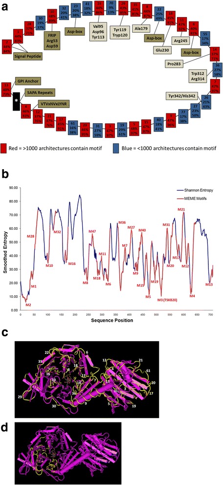
Fig. 2.

Analysis of Model TcTS Architecture. a The model TcTS architecture (starting with the signal peptide motifs) is depicted. Each box represents an individual motif from the MEME analysis. The top number is the motif number, the middle percentage is the representation of that motif across all TcTS sequences (including where absent), and the bottom number is the representation of that motif in TcTS sequences of length >2000b. Frequent motifs (>1000 occurrences in all TcTS sequences) are color-coded red, while less frequent motifs are blue. The highly-variable C-terminal region containing multiple motifs is represented as a black box. Locations of previously characterized TcTS motifs and residues are also shown. b An entropy analysis of TcTS sequences is shown. The smoothed entropy values for selected TcTS proteins is plotted against amino acid position. Using sequence homology of the motifs in this study to the protein sequences of the entropy study, locations of the motifs are overlaid in the chart (in red). Note that lower-numbered motifs are typically found in areas of low entropy. c The crystal structure of TcTS “1S0I_A” with motif regions highlighted and labeled and d) a notable region lacking in motifs (see Additional file 11: Figure S5 for diagram of motifs mapped to the crystal structure)
