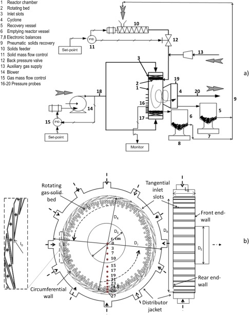
Figure 1.

(a) Schematic diagram of the GSVR setup. (b) Detailed view of the GSVR and the location of the pressure taps at the Plexiglas end‐wall of the GSVR (Adapted from Ref. 28).
[Color figure can be viewed in the online issue, which is available at wileyonlinelibrary.com.]
