
Figure 10.
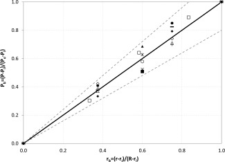
Normalized pressure profile in the bed as a function of normalized radial coordinates for HDPE (950 kg/m3): 1 mm, 2 kg, 85 m/s (○);1.5 mm, 2 kg, 55 m/s (▪); 1.5 mm, 3 kg, 70 m/s (Δ); 1.5 mm, 3 kg, 110 m/s (+); 1.5 mm, 4 kg, 55 m/s (⋄); 1.5 mm, maximum capacity, 70 m/s (□); 2 mm, 2 kg, 70 m/s (∗); and for PC (1240 kg/m3), 2 mm: 2 kg, 55 m/s (×); 3 kg, 70 m/s (▲); 4 kg, 70 m/s (♦); 4 kg, 100 m/s (•); maximum capacity, 70 m/s (−).
The continuous line represents the fitting line P b = r b. Dotted lines represent standard deviation of ±20%. A gas injection velocity change indicates a change of gas flow rate, given that the slot thickness is constant in all experiments.