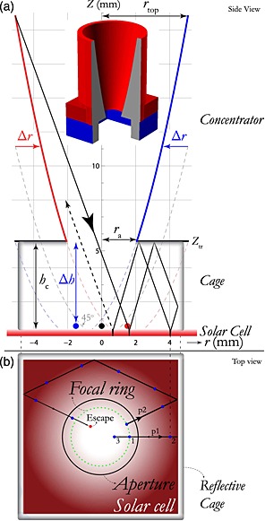
Figure 3.

(a) A vertical cross section through the symmetry axis of the light trap. The compound parabolic concentrator (CPC) is rotationally symmetric, the cage is a cuboid. The light impacting the left side of the CPC is focused on the right red focal point and vice versa for blue. The inset shows a 3D model of the design: a circular CPC is placed directly on top of the square cage. (b) Top view of the square cage. Because of the rotational symmetry of the CPC, the focal points form a focal ring (indicated in green). Two horizontal projections of different light paths are shown. The blue dots indicate the spots where the light is reflected by the solar cell. Path p1 corresponds with that shown in Figure 3(a). Light following path p2 travels a longer distance and thus hits the cell more often compared with p1. The distance between the spots depends on the polar angle with the z axis. This in turn depends on the radial location where the initial beam hits the paraboloid.
