
Figure 1.
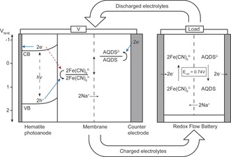
Energy diagram of the PEC/RF cell for solar charging of electrolytes connected to a RF cell for discharge. Desired electron‐hole pathways under light exposure are shown with full blue arrows. Undesirable back‐electron transfer is shown with red dotted arrow.