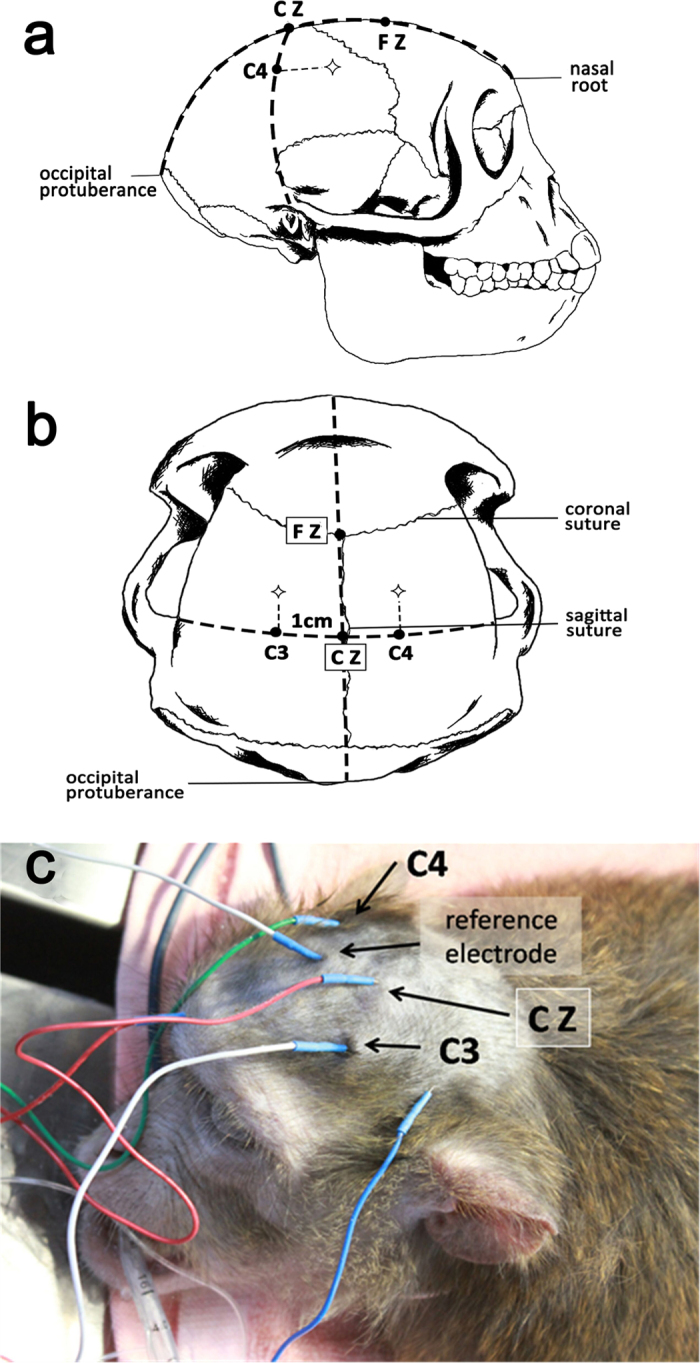
Figure 4. The location of electrodes inserted and the stimulating area.

(a) The anterior-posterior (AP) sagittal line: made a line from the nasal root to the external occipital protuberance and took five points formerly backward, in turn named as Fpz, Fz, Cz, Pz and Oz. The distances of the Fpz to the nasal root and the Oz to the external occipital protuberance respectively comprised about 10% of this line and the others were equality apart by 20% of the line. (b) The transverse line: made another line from the left pre-auricular to the right pre-auricular which intersected the AP sagittal line at Cz. Then we took two points on each side of the transverse line, T3 (Not marked in the picture) and C3 on the left, T4 (Not marked in the picture) and C4 on the right. The distances of T3 to the left pre-auricular and T4 to the right pre-auricular respectively comprised about 10% of the transverse line and the others were equality apart by 20% of the line (include the point Cz). (c) As this actual picture showed that during the TES-MEPs monitoring the stimulating electrodes placed about 1 cm in front of C3 and C4, they were each other’s reference electrode. During the SSEPs monitoring, the receiving electrode placed at Cz and the reference point placed at random point.
