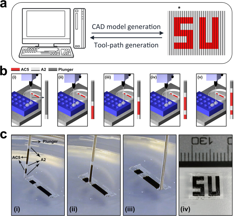
Figure 1. Schematic representation of printing process for deposition of a patterned structure.
(a) CAD model is generated in an appropriate software and tool-path is developed by considering the material switching orders. (b) Aspiration orders are assigned to the computer-controlled aspiration/deposition system which is installed on a three-axis platform. Step-by-step aspiration of a filament is shown with respect to its build sequence defined in the CAD model (marked by asterisk in panel (a)). (c) (i–iii) real-time images captured during printing of a complex pattern. Aspirated filament in (i) consists of five different ink segments. (iv) Printed SU (Sabanci University) logo which includes segments of A2 (transparent) and AC5 (black) inks.

