Figure 5.
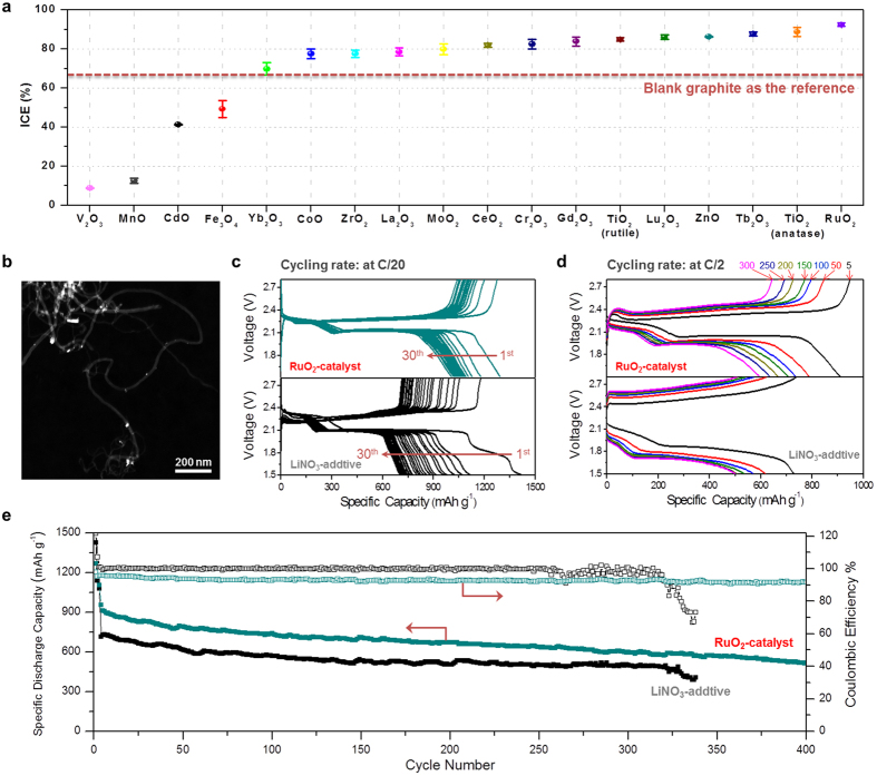
(a) ICE data of the Li-S cells with the introduction of different transition metal oxides on graphite substrate. (b) HAADF-STEM image of RuO2-MWCNTs composite. (c,d) Galvanostatic discharge-charge voltage profiles of the cell with RuO2 catalyst cycled in LiNO3-free electrolyte (top) and the bared MWCNTs-sulfur electrode cycled in the electrolyte with 2.0 wt% of LiNO3 additive (bottom) at the cycling rate of C/20 (from 1st to 30th cycle) and C/2 (in 5th, 50th, 100th, 150th, 200th, 250th and 300th cycle). (e) Comparison of the cycling performance of the cell with RuO2 catalyst and that with LiNO3 additive (at C/2). The cells were first stabilized at C/20 for 3 times.

