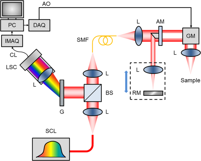
Figure 7. μOCT instrumentation.
Schematic diagram of μOCT system. Supercontinuum laser (SCL) power is directed by collimating and focusing lenses (L) through a single mode fiber (SMF). Output light from the SMF is collimated and passed through an apodizing mirror (AM), resulting in a circular obscuration of the transmitted light, which is steered by a galvanometer mirror (GM) through an objective lens onto the sample. Light reflected by the AM is focused onto a reference mirror (RM), and the reference lens and mirror assembly can be translated in unison to adjust the reference path length. Back-scattered light from the sample is re-integrated at the SMF with light reflected by the RM. The return light is collimated and directed by the beam-splitter (BS) towards a diffraction grating (G). The spectrally dispersed light is then focused onto a line scan camera (LSC), which outputs raw spectrograms through a CameraLink (CL) interface to an image acquisition board (IMAQ) installed in a PC. The PC also controls scanning through a data acquisition card (DAQ), which produces an analog output (AO) voltage signal that controls the GM.

