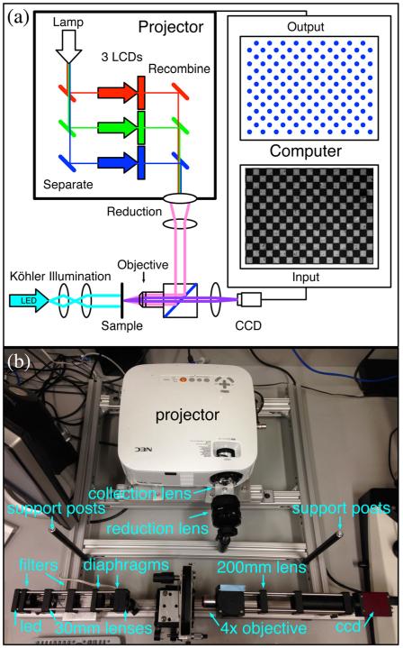
Fig. 1.
(a) A schematic illustration and (b) a photograph of the optics of the Programmable Illumination Microscope (PIM). Light from the projector exits the projector through the stock lens in reverse and is defocused to infinity using the lens from a 35-mm camera. The parallel light is transmitted into the beam cube, reflected from a beamsplitter, and focused through the ×4 microscope objective to illuminate in reflection. The sample is imaged with a 200-mm lens onto a CCD camera. An optional Köhler illumination setup is in place to illuminate the sample in transmission (a cyan LED in conjunction with a neutral density filter and 510-nm bandpass filter focused using two 30-mm lenses with ring-activated iris field and aperture diaphragms). A neutral density filter is taped to the beam cube to attenuate the intensity of light from the projector and support posts for the blackout cage are mounted to the supporting frame. The computer (not shown) calculates a dot for every white square in the 100-μm checkerboard alignment grid. The exact layout of the optics is shown in Fig. 9.

