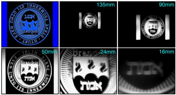
Fig. 2.
The overlap of the field of projection with the field of view is controllable by changing the focal length of the reduction lens [see Fig. 1(b)] used in the PIM. Examples are shown of the overlap using reduction lenses of different focal lengths. The exact overlap will also depend on the focusing lens used and the sensor size of the CCD. Top left: The image being projected onto a clean silicon wafer. Note that the Brandeis logo is upside down in the projection. Using a 135-mm or 90-mm lens results in the field of projection being smaller than the field of view. Using a 24-mm or 16-mm lens results in the field of view being smaller than the field of projection. Using a 50-mm lens results in a nearly perfect overlap of the fields of view and projection.

