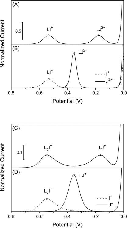
Figure 2.
Thin-layer voltammograms (solid and dashed lines) as simulated by using (A and B) β1 = 109 for I+ and β1 = 1012 for J+ and (C and D) β2 = 109 for I+ and β1 = 106 for J2+ in addition to [IzI]W =[JzI]W = LT = 1 M for simplicity. The potential is defined against . Closed circles represent the current and potential of a voltammetric peak based on the IE mechanism as calculated by using eq 10 and 11, respectively. Closed circles are based on the IT mechanism and obtained by using eqs 14 and 15.

