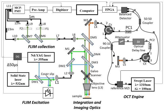
Fig. 1.
Schematic of OCT_FLIM system. Green line represents the excitation beam for exogenous FLIM; Blue line is the excitation beam for endogenous FLIM; Olive line is the emission; Maroon line is the beam for OCT. Note that overlapping co-linear beams are shown as parallel lines for clarity. The thin grey line is the trigger path. DM1-DM7: Dichroic Mirrors, L1-L10: Lenses, M1-M2:Mirror, PC1-PC2:Polarization controller, F1-F2:Longpass and bandpass filters, MCP-PMT-Multi-channel plate photo multiplier tube, Pre-Amp-Pre-amplifier, MZI-Mach Zehender Interferometer, FPGA- Field Programmable Gate Array, DG-Delay Generator.

