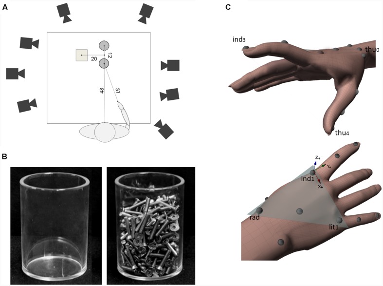
FIGURE 1.
Experimental set-up and hand models for kinematics parameters computation. (A) A schematic representation of the top view of the experimental set-up (not to scale). The position of the object in real grasp task and in pantomimed grasp task is indicated with a filled and a dashed line circle, respectively. Distances are provided in centimeters. (B) A picture of light and heavy object used as target objects. (C) The hand model used to compute kinematics parameters together with a graphical representation of the local frame of reference (Flocal). Flocal had its origin in the marker placed at the metacarpo-phalangeal joint of the index (see ind1). Vectors (ind1 – lit1) and (ind1 – rad) defined the metacarpal plane of the hand (shaded triangle). In this frame of reference, the x-axis had the direction of the vector (ind1 – lit1; refer to the red arrow) and pointed ulnarly, the z-axis was normal to the metacarpal-phalangeal plane, pointing dorsally (refer to the blue arrow), while the y-axis was calculated as the cross-product of z- and x-axes, pointing distally (refer to the green arrow).

