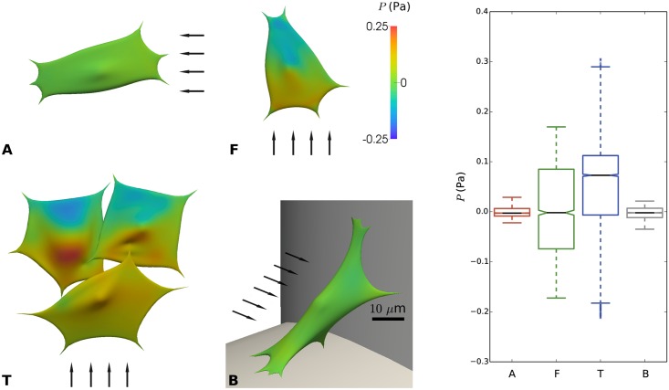
Fig 8. Pressure (P) on the cell surface due to imposed flow for distinct configurations (A, F, T and B) of cells on scaffold struts.
Left: color maps showing local pressure. The arrows indicate the direction of the flow; scale bar 10 μm. Right: boxplot showing distribution of pressure for cases A, F, T and B.

