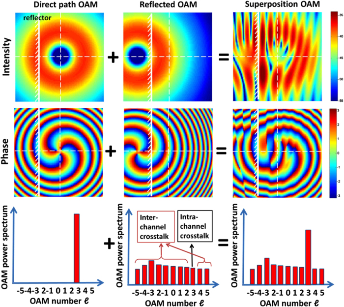
Figure 3. Simulation results showing the intensity, phase, and OAM spectrum of the direct path OAM beam, reflected path OAM beam, and the actual beam at the receiver.
The actual beam is the superposition of the direct OAM and the reflected OAM beams. Because the reflected OAM beam is along the off-axis, it is no longer orthogonal to the OAM beams in the direct path and is likely to cause both inter-channel and intra-channel crosstalk at the receiver. The white solid line represents the reflector.

