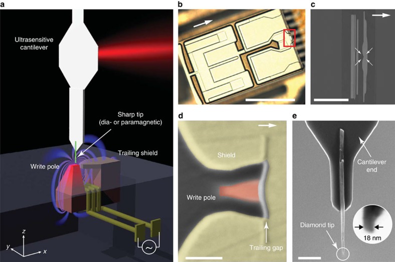
Figure 1. Geometry of write head experiment and device.
(a) A sharp diamond needle (green), attached to a nanomechanical force transducer, is positioned over the write pole of a magnetic recording head. An alternating current periodically switches the pole polarity and induces magnetic gradient forces through dia- or paramagnetism in the tip. Experiments are carried out in a custom scanning force microscope operating at 4 K and in high vacuum. (b) Optical micrograph of the write head device. Arrows in b, c and d point in the direction of the trailing edge (in positive x direction). The write head was extracted from a commercial Seagate hard drive, reconnected to external leads and mounted in the apparatus as discussed in the Methods section. Scale bar, 0.5 mm. (c) Zoom-in on the write/read region of the device. The write pole is at the centre of the four arrows. Scale bar, 20 μm. (d) The ∼90 × 60 nm2 write pole (red) is surrounded by a return shield (yellow) that serves to recollect the field lines. The gradient is largest in the ∼20-nm-wide trailing gap between pole and shield. Scale bar, 100 nm. (e) Diamond nanowire probe attached to the end of an audio frequency (∼5 kHz) silicon cantilever. Inset shows apex of tip B. Scale bar, 2 μm.

