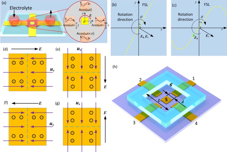
FIG. 1.
Three dimensional schematic of the experimental setup. (a) Four strip ITO driving electrodes with a quadrature configuration are patterned on a glass substrate. The nearest interelectrode distance along the x- or y-direction is L = 2 mm. A metal square of edge length d = 300 μm and negligible thickness is placed at the centre of four driving electrodes. A PDMS channel of 500 μm height with two electrolyte ports is reversibly bonded to the glass substrate with patterned electrodes to form a closed microfluidic chamber. A KCl electrolyte solution containing particle tracers or target particle samples is injected into the channel and finally fills the microchamber. A background rotating electric field in the clockwise direction is nearly unaffected by the presence of the square floating electrode in the DC limit. (b) and (c) Transient behaviour of ROT-ICEO. (b) Phase diagram of the background field Eb, inducing surface tangential field Et and FSL in the DC limit. (c) Phase diagram at slightly above the RC charging frequency. (d)–(g) The two dimensional phase diagram for the rotating FSL (dashed line) of ROT-ICEO occurring above a planar metal surface in a background rotating electric field. Transient ionic charge polarity and slip flow direction at different time instants: (d) t = 0; (e) t = T/4; (f) t = T/2; (g) t = 3 T/4. (h) The 3D geometrical model applied in numerical simulation (not to scale).

