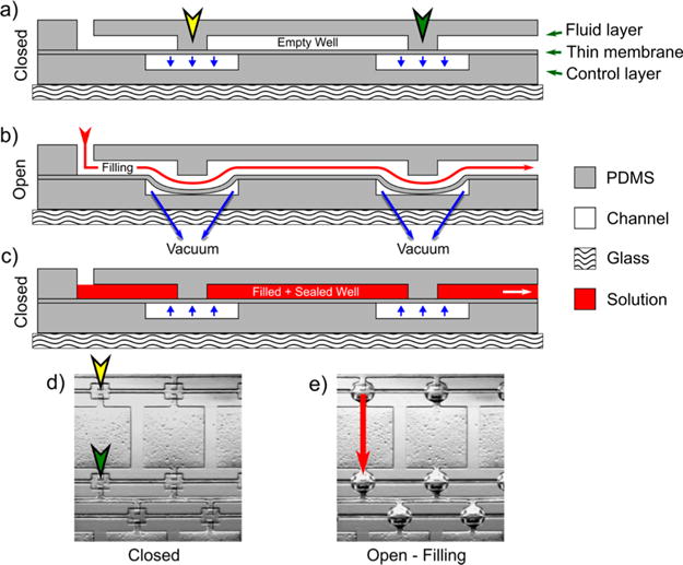
Figure 2.

“Doormat” valve schematic applied to PDMS channels and the filling process. (a) The three-layer device is shown in the normally closed state with no pressure applied, blocking the channels. (b) During filling, a vacuum is applied to the control layer which allows the thin membrane to deflect downward (due to not being strongly bonded to the fluid layer), opening a pathway between the channels for fluid to flow (designated by the red arrow). (c) Once the device is filled, the vacuum is removed, causing the thin membrane to return to its original state, isolating the wells from one another for crystallization. (d) Bright-field image of a PDMS replica when the valve is closed, showing the blocked channels, marked with corresponding locations on the schematic in (a). (e) Bright-field image of the PDMS replica of the device when the valve is actuated, showing the protruded PDMS membrane and red arrow marking the filling pathway. The speckles in the wells relate to defects due to the photolithography process.
