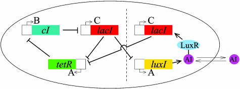
Fig. 1.
Scheme of the repressilator network coupled to a quorum-sensing mechanism. The original repressilator module is located at the left of the vertical dashed line, and the new coupling module appears at the right. The letters A, B, and C correspond to the notation used in the text. The coupling module can be added to existing repressilator strains.

