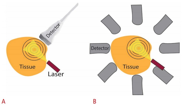
Fig. 2. Photoacoustic imaging configurations.

Laser source and the detectors may be on the same side or at an angle to each other. However, an overlap must exist between the laser beam and the detector’s directivity pattern to ensure that laser-induced ultrasound signals are detected and visualized. A. Photoacoustic imaging performed with a conventional ultrasound transducer where only a portion of the spherical wavefront (black rings) originated from the target (red absorber at the center of the rings) is seen by the transducer. B. Photoacoustic tomography approach showing X-ray computed tomography–like reconstruction where a single detector can be rotated around the target or an array of multiple stationary detector elements around the target can be employed. The signal arriving at each detector is filtered back-projected along circular arcs in the spatial domain, and then all the back-projections are added together to obtain the final photoacoustic image which represents the spatial distribution of optical absorption within the target.
