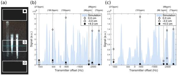
Figure 3.
Signal intensity measurements of the SPSP RF pulse performance on slabs above, below, and through a 13C-urea phantom. (a) Sketch of the 2-cm-slab positions on the three syringes filled with a 13C-urea solution used as a phantom. (b) Six-band SPSP RF pulse performance. RF flip = 29° was calibrated at the transmitter frequency −2928 Hz (tdel=−4 us). (c) Five-band SPSP RF pulse performance. RF flip = 20° calibrated at the transmitter frequency −2895 Hz (tdel=−4 us). These calibration frequencies correspond to the G3P resonance as targeted in each pulse design. Shaded area is the simulated signal in the slab through the phantom.

