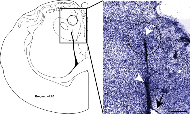
Fig 1. Cannulae placement verification.
Left, A schematic of the brain section from Paxinos and Watson [40]. Right, A representative photomicrograph of cresyl violet-stained brain slice (75 μm-thick) used to confirm cannulae placements in the NAc shell. Dotted circle (1 mm diameter) represents the maximal diffusion area for a 0.5 μl solution volume [41]. Black arrow–tip of the guide cannula. White arrow–tip of the microinjector. White arrowhead–lateral ventricle. AC–anterior commissure. Scale bar, 0.5 mm.

