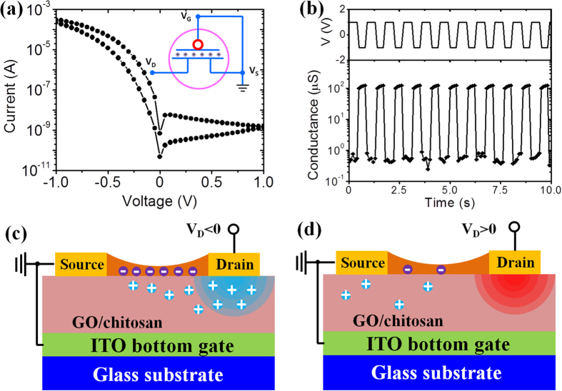
Figure 3. Two-terminal operation of the device.
(a) Current-voltage curve of the device. Absolute value of the current is used. Inset is the schematic illustration of two-terminal operation. (b) Switching characteristics of the device. The channel conductance is recorded (the bottom panel) simultaneously when the drain voltage is switching between 1.0 and −1.0 V (the top panel). (c), (d) Schematics of the working mechanism (Drawn by C.W.). When the drain voltage is negative, protons will be attracted below the channel layer, inducing free electrons in the channel layer due to the EDL effect; however, when the drain voltage is positive, protons will be pushed away from the channel, and thus there are fewer electrons in the channel layer.

