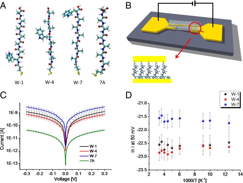
Fig. 1.
Scheme of experimental setup and results of current–voltage measurements. (A) Structure of peptides used: W-1: MPA-WAAAAAA; W-4: MPA-AAAWAAA; W-7: MPA-AAAAAAW; 7A: MPA-AAAAAAA (A = alanine, W = tryptophan). MPA is attached at the peptides’ N terminus. (B) Schematic drawing of Au–peptide–Au junction setup. A peptide monolayer-covered Au NW is suspended on top of two Au electrodes to form the closed circuit. (C) Current–voltage plots at 300 K for Au–peptide–Au junctions of W-1, W-4, W-7, and 7A. Each plot is the average of ∼20 curves. (D) Temperature-dependent currents at 50 mV measured as function of 1,000/T through W-1, W-4, and W-7.

