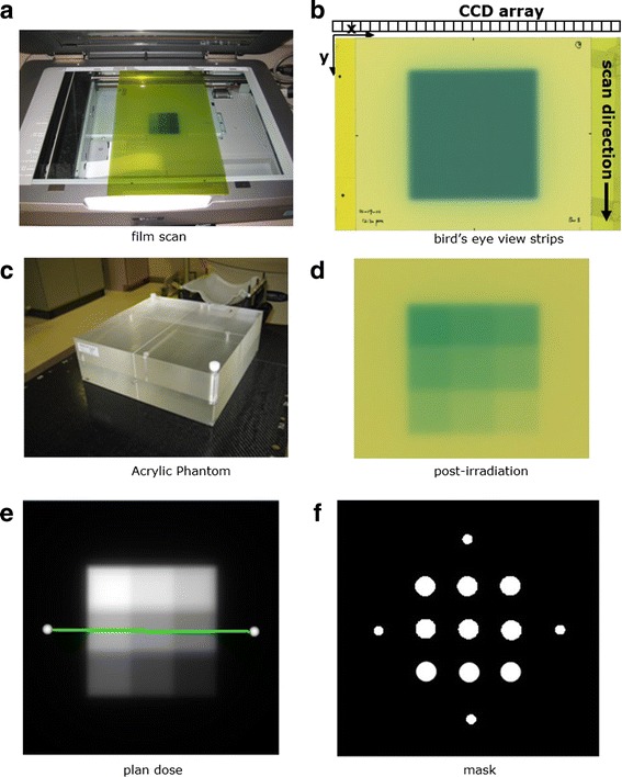
Fig. 1.

a film scanning orientation with the longer side of film aligned to the scanner detector array. b A bird’s eye view of film scanning orientation with film strips attached for positioning accuracy. c Acrylic phantom for film dose calibration. d A calibration film irradiated with a nine 2 × 2 cm2 square dose pattern. e The corresponding planar isodose distribution. f A mask pattern used to sample optical density values to establish the calibration curve
