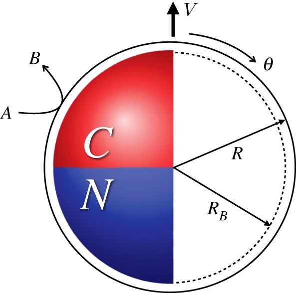
Figure 1.

A Janus motor with catalytic (C) and non-catalytic (N) faces. The catalytic face converts fuel A to product B. The motor is propelled in the direction of  which is taken to lie along the polar z-axis in a spherical polar coordinate system with polar angle θ. The left part of the figure shows the geometry used in the continuum model. The solid outer circle denotes the outer edge of the boundary layer at radius R. The right part of the figure shows the geometry used in the microscopic hard bounce-back model. The inner dashed circle indicates the radius at which bounce-back collisions of B particles take place, whereas the outer solid circle, which coincides with the outer edge of the boundary layer, is the bounce-back radius for A particles. (Online version in colour.)
