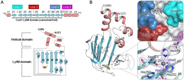
Fig 5. Overall monomer structure of H. pylori Csd1125–312.
(A) Schematic representation of secondary structures of Csd1125–312 and topology diagram of Csd1125–312. Secondary structures have been defined by the STRIDE program [42]. α-Helices, β-strands, 310-helices, and loops are shown as cylinders (colored in light pink), arrows (blue-green), flat cylinders (yellow), and solid lines (grey), respectively. Loop 1 (β1-β2 loop; cyan), Loop 2 (β4-β5 loop; red), Loop 3 (β8-β9 loop; skyblue), and Loop 4 (β9-β10 loop; purple) form the substrate-binding groove of the Csd1 LytM domain. Dotted lines indicate disordered regions. (B) Ribbon diagram of Csd1125–312 monomer structure (chain C of Csd1-Csd2 dimer I), colored as in the topology diagram in Fig 5A. Close-up views on the right represent the surface representation of the substrate-binding groove formed by four loops of the LytM domain (top) and canonical Zn2+-coordination with three protein ligands and two water molecules (bottom). Dark grey and red spheres represent a Zn2+ ion and water molecules, respectively. Side chains of the Zn2+-coordinating residues (His169, Asp173, and His252) are shown in stick models. Black dotted lines denote penta-coordination of the Zn2+ ion. The electron density for the Zn2+-bound active site in 2mFo − DFc map (grey colored mesh) are shown at the 1.0 σ level.

