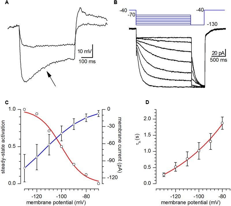
FIGURE 4.

h-current. (A) Response of a CR-GFP neuron under current-clamp condition to the injection of 5 and 15 pA hyperpolarizing current pulses. Note the appearance of the archetypal sag (arrow) due to the activation of Ih; bath solution for this recording was standard ACSF. (B) Family of responses of a CR-GFP neuron under voltage-clamp conditions to the application of the double pulse protocol shown in the inset above; explanation in the text; bath solution EC2. (C) Current–voltage relationship of the h-current (blue line, right y-axis) and voltage-dependence of the activation curve (red line, left y-axis) obtained from tail analysis of double-pulse experiments as shown in (B); mean value ± SE; (n = 20). (D). Ih activation time constant as a function of membrane potential; the continuous line, phenomenological description of τh in the voltage interval shown, obeys the equation τh(V) = 5908 ∗ exp[-V/(-51.82) - 677.48].
