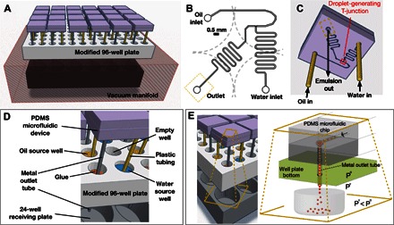
Fig. 1. Overview of the droplet screening platform.

(A) Schematic summary of the microfluidic screening platform, which includes 24 PDMS droplet-based microfluidic devices, a modified 96-well microtiter plate to hold water and oil source solutions and interface PDMS devices with a vacuum manifold, and a commercial vacuum manifold including a 24-well capture plate in its interior. See photograph of the system in fig. S1. (B) Schematic top plan view of the microfluidic device design, indicating the position of the device’s T-junction, inlets, and outlet relative to four adjacent 96-well plate wells (dotted lines) below the device. (C) Schematic image showing the direction of fluid flows through each microfluidic device. For illustration, an approximate microfluidic channel pattern is projected on the bottom surface of the device [channels actually reside at the interface between two PDMS slabs, and accurate microfluidic pattern dimensions are shown in (B) and in Fig. 2A]. (D) Magnified schematic view of one microfluidic device within the platform, highlighting relevant platform components. (E) Fluid flow through each microfluidic chip is motivated by a pressure differential across an exit tube connected to the chip’s outlet (at pressure Po) that opens into a pressure-regulated vacuum environment, over a receiving well (at Pressure Pv) that collects the emulsion (or separated biphasic solution).
