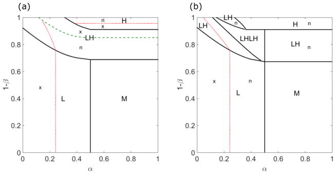
FIG. 9.
The phase diagrams for low [(a), 0.1 s−1] and high [(b), 0.5 s−1] switching rates. The phases are L (low density), M (Meissner), H (high density), LH (low-density–high-density coexistence), and LHLH (low-density–high-density–low-density–high-density coexistence). The thick green dashed line indicates where the domain wall position xw = 0, which separates regions with a local maximum of the central density (x) or local minimum (n). The red dashed lines indicate boundaries between local maximum and minimum phases. For low switching rate, the left parts of the L and LH phases are local maximum phases, and the right are local minimum phases. The upper part in the H phase is local minimum phase. For high switching rate, the left parts of the L and LH phases are local maximum phases, and the right parts are local minimum phases. The bulk motor concentration is c = 200 nM, and the motor speed 5 μm s−1; other parameters are the reference values of Table I.

