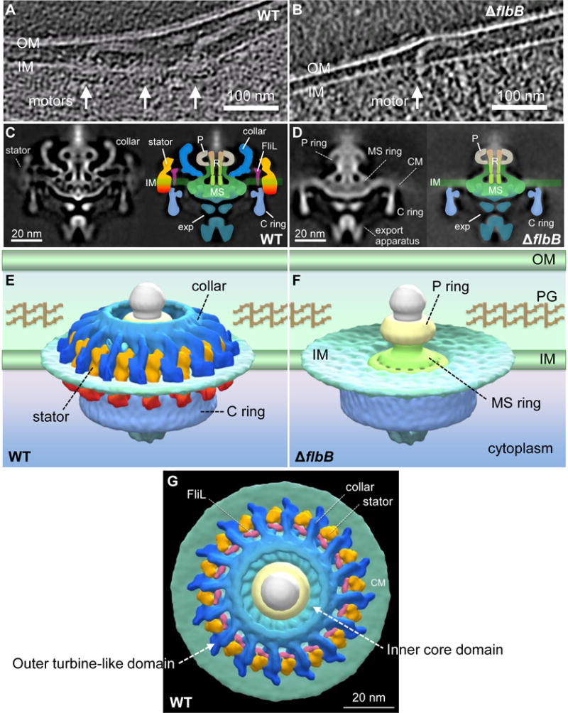
Figure 4. Comparative analysis of in situ flagellar motors from wild-type and ΔflbB reveals the 3D collar structure for the first time.

(A) A tomographic section from a WT cell shows the motors that are embedded in the cytoplasmic inner membrane (IM/CM). (B) A tomographic section from a ΔflbB cell shows a motor that is embedded in the cytoplasmic membrane. (C) The central section (left) and schematic diagram (right) of the WT flagellar motor. (D) The central section (left) and schematic diagram (right) of the ΔflbB flagellar motor. (E) The surface rendering of the 3D averaged WT and (F) ΔflbB motor structures are shown in side view. (G) The surface rendering of the 3D averaged WT motor structure is shown in tilted top view (90°). Compared to the motor structures from WT (C, E, G), the ΔflbB motor lacks the entire collar (blue), the stator (orange-red), and FliL (pink) structures. Noticeably, the collar is a large and complex structure comparing to FliL and the stator. OM, outer membrane; PG, peptidoglycan; P, P-ring; R, central rod; exp, export apparatus.
