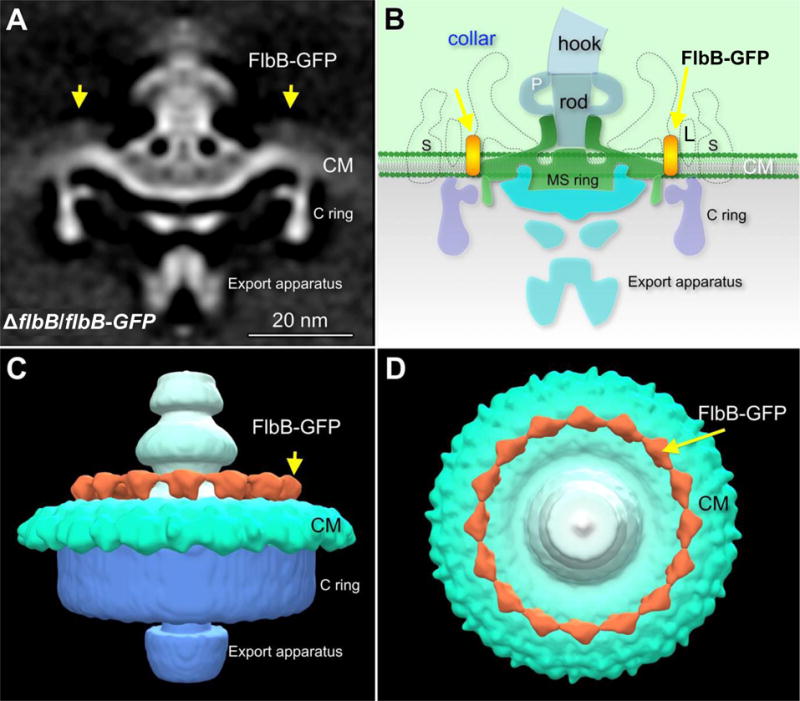
Figure 7. Location of FlbB-GFP as determined by cryo-ET.

(A) The averaged 3D motor structures of the ΔflbB cells expressing FlbB-GFP (ΔflbB/flbB-GFP), and (B) schematic diagram of the ΔflbB/flbB-GFP flagellar motor illustrating the location of FlbB at the base of the collar. (C) Three dimensional isosurface rendering of the ΔflbB/flbB-GFP flagellar motor is shown in side view. (D) Three dimensional isosurface rendering of the ΔflbB/flbB-GFP flagellar motor is shown in tilted (top) view. The yellow arrows indicate the location of FlbB-GFP. S, stator; L, FliL; P, P-ring.
