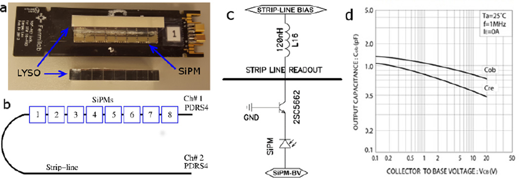
Figure 1.
(a) A strip-line board (SLB#1). A linear array of eight LYSO scintillators is coupled to 8 SiPMs on a strip-line on the board. (b) The numbering of SiPMs on a strip-line and PDRS4 readout channel assignment. (c) A schematic diagram shows the biasing scheme for a buffer transistor (ROHM 2SC5662). Two strip-line boards are used in this work and the strip-line bias is 0 V for SLB#1 and 0.6 V for SLB#2. (d) The output capacitance vs. bias voltage for the 2SC5662 transistor across the collector and base [24].

