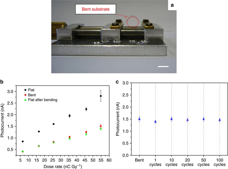
Figure 4. Assessment of the mechanical reliability of the system.
(a) Experimental set-up used for the characterization of the detector during bending (scale bar: 1 cm). (b) Photocurrent as a function of dose rate of a device measured before bending (black solid squares), during bending with a bending radius of 0.3 cm (red solid circles) and after bending (green solid triangles). (c) Photocurrent of a device measured under bending and in flat-substrate condition after the 1, 10, 20, 50 and 100 bending cycles, at the same bending radius R=0.3 cm. The device (W=26 mm; L=30 μm), biased at 0.5 V, is irradiated under an X-ray beam provided by a Mo-tube with 35 kV of accelerating voltage and a dose rate of 55 mGy s−1.

