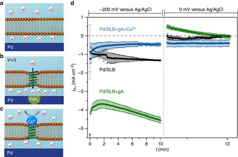
Figure 2. Schematics of bioprotonic gA devices.
(a) Pd contact coated with a SLB. The SLB inhibits the flux of H+ from the bulk solution to the Pd/solution interface. (b) Pd contact with SLB incorporating gA is semipermeable to H+, with gA channels facilitating the rapid flow of H+ to the Pd/solution interface. (c) Addition of 1 mM Ca2+ to the bulk solution, blocks gA and prevents the flow of H+ to the Pd/solution interface. (d) iH+ versus time plot for V=−200 mV and V=0 mV. Black trace SLB, green trace SLB+gA, blue trace SLB+gA blocked by Ca2+. (The data are collected from 3 different devices with different dimensions: Pd / SLB: 3 different devices of 2 × 50 μm, Pd/SLB+gA: 2 × 20 μm, 2 × 50 μm, 2 × 70 μm, Pd/SLB+gA+Ca2+: 2 different devices of 2 × 50 μm and 1 device of 2 × 70 μm. The error bars are the root mean square of the displacement of the data from the average value).

