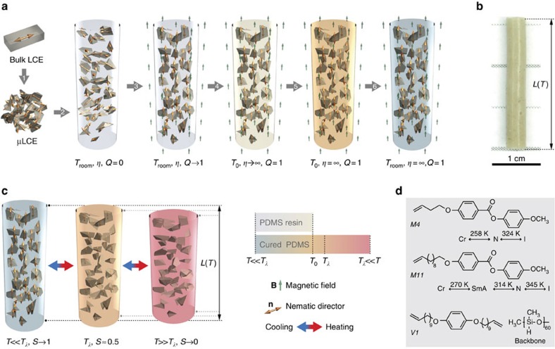
Figure 1. Preparation of a PDLCE composite.
(a) Schematic illustration of the six-step PDLCE manufacturing method: (1) crushing the starting bulk LCE into μLCE particles, (2) dispersing the particles in uncured (low viscosity η) PDMS elastomer, (3) aligning the initially disordered μLCE in external magnetic field, that is, increasing μLCE orientational order from Q=0 to Q=1, (4) heating to setting temperature T0, (5) thermal curing of PDMS matrix at T0, and (6) cooling the resulting PDLCE composite to Troom. (b) Photograph of a representative, cylindrically shaped PDLCE-A specimen, prepared according to the method shown in a (see Methods for composition and fabrication details). (c) Spontaneous mechanical deformation of PDLCE composite on crossing the nominal thermomechanical anomaly temperature Tλ of μLCE filler, associated with the change in the nematic order parameter S. Also shown is the colour bar used to colour-code the temperature of PDMS matrix in panels a and c. (d) Chemical structure of LCE material constituents: nematic M4 and smectic A M11 mesogenic side-chains with their respective bulk phase transition temperatures between the isotropic (I), nematic (N), smectic A (SmA) and crystalline solid (Cr) states, bi-functional crosslinker V1, and (poly)methylsiloxane backbone. For animated version of the μLCE alignment procedure (a) and of thermomechanical actuation (c) play the Supplementary Movie 1.

