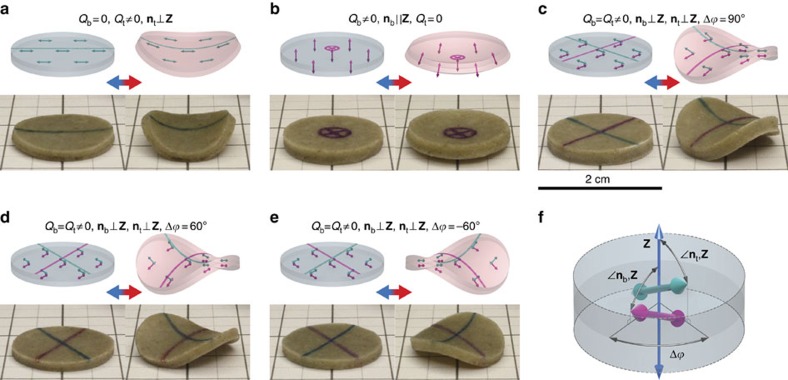
Figure 5. Programmable shape memory of PDLCEs with bilayer director field.
Desirable thermomechanical response is instilled by configuring μLCE orientational order Q and orientation of nematic director n in the top and bottom PDLCE layers (indices t and b), respectively. All basic thermomechanical actuation modes, specifically bend deformation (a), cup deformation (b), saddle deformation (c), as well as left twist (d) and right twist (e) deformation can be realized by a suitable choice of Qt and Qb, of the orientation of nt (cyan double arrows) and nb (magenta double arrows) with respect to the surface normal Z of the sample, as well as of the relative azimuth Δ between nt and nb(f). In each of panels a–e, the particular μLCE configuration and anticipated sample shape is depicted schematically in the two icons at the top, with the left one representing low-temperature state (T<Tλ, blue-tinted PDMS matrix) and the right one representing high-temperature state (T>Tλ, red-tinted PDMS matrix). Temperature-controlled shape morphing of real PDLCE-A bilayer samples is demonstrated with respective photographs at the bottom of panels a–e, the left one showing the specimen at T=300 K and the right one showing the specimen at T=400 K. Cyan (top layer) and magenta (bottom layer) solid lines and cross-hairs mark the respective directions of macroscopic thermomechanical anisotropy axes.

