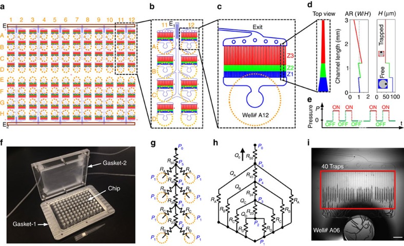
Figure 2. Multi-well microfluidic chip design for C. elegans trapping and imaging.
(a) Schematic of the 96-well chip design with two common exit lines (E1 and E2) along chip edges. (b) A repeating unit of 4 × 2 wells connected to the common exit port E1. (c) A single well and its immobilization channels with varying aspect ratios ( =width/height) in zone 1 (Z1), zone 2 (Z2), and zone 3 (Z3). (d) The top view of the trapping channel and its height (H) and
  for all three zones as a function of the length. The schematic of the cross-sections of a free and trapped animal is shown at different regions of the trapping channel with the green dots showing the location of their ventral cord position. (e) Animals are pushed into the trapping channels using an on/off pressure cycle. (f) An image of 96-well chip with the gasket system. (g) The map of hydraulic resistances for 40 traps with varying exit channel widths (RA, RB, RC, and RD) and main exit channel sections (R23, R34, R45, and R50). (h) The equivalent resistance circuit under a common gasket pressure P1 and resulting flow rates (QA, QB, QC, QD, and Q0). The pressure at the exit port P0 is assumed to be an atmospheric pressure. (i) An image of 40 trapping channels with immobilized animals. Scale bar is 1 mm.

