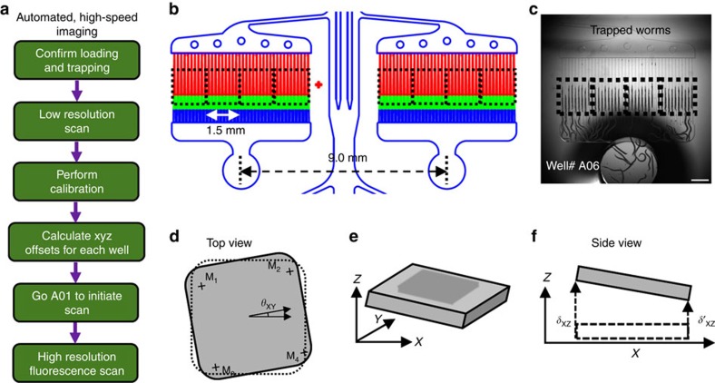
Figure 3. Automation for high-speed image acquisition from multi-well chip.
(a) Flow chart of the automated imaging. (b) Parallel traps are imaged with a large camera to capture a 1.5 × 1.5 mm2 portion of the chip with 10 parallel traps and moved in a synchronized manner to capture multiple image stacks at every location. (c) An image of well# A06 with all its 40 immobilization channels, showing trapped D3 adult animals and four 1.5 × 1.5 mm2 FOVs with 10 parallel traps each (black dotted rectangles). Scale bar is 1 mm. (d) Top view of the chip showing four corner markers (M1, M2, M3, and M4) and the rotational offset (θXY). (e) The schematic of the chip overall tilt (δXY and δXZ) when mounted on the stage. (f) Side view of chip mounted with XZ tilt (δXZ).

