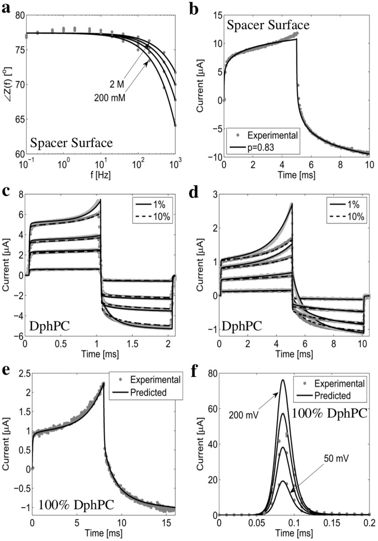
Fig 4. Experimentally measured and numerically computed current response of the tethered membrane.
(a) and (b) provide the measured and computed phase and current response of the spacer surface. Note Cm → ∞ and Gm = 0 as the membrane is not present. (c) to (f) provide the experimentally measured and numerically computed current response I(t) for 1%, 10%, and 100% tethered DphPC membranes. In (c) the drive potential Vs(t) is defined by a 1 ms linearly increasing potential with a slope of 10 V/s, 40 V/s, 70 V/s, and 90 V/s followed by a 1 ms linearly decreasing potential with identical slope. In (d) Vs(t) is a 5 ms linearly increasing potential with slope of 50 V/s, 200 V/s, 300 V/s, and 450 V/s followed by a 5 ms linearly decreasing potential with identical slope. In (e) Vs(t) is defined by a 8 ms linearly increasing potential with a slope of 100 V/s followed by a 8 ms decreasing potential with identical slope. In (f) Vs(t) is a step of 50 mV, 100 mV, 150 mV, and 200 mV. All numerical results are computed using the fractional order macroscopic model provided in the S1 Text.

