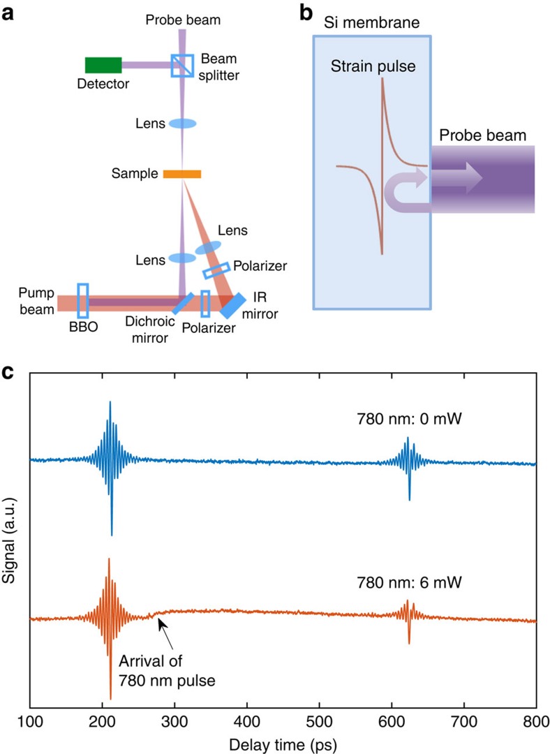
Figure 1. Overview of the experiment.
(a) Schematic of the experimental set-up. Not shown are components of the set-up standard for ultrafast optical pump–probe experiments such as the laser, the optical delay line and so on. (b) Schematic showing the strain pulse generated by the pump pulse in a silicon membrane, and the generation of Brillouin oscillations: interference of probe light reflected from the sample surface and the strain pulse. (c) Typical signal (the first two echoes) without the 780 nm excitation beam and with 6 mW of 780 nm excitation. The arrow marks the time delay at which the 780 nm excitation pulse arrives. The slow transient after the arrival of the 780 nm excitation is due to the carrier generation. IR, infrared; BBO, bismuth borate.

