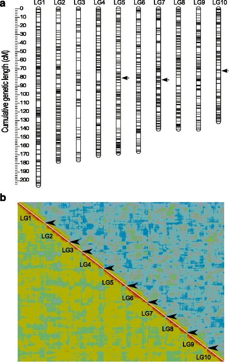
Fig. 1.

a Linkage length and marker distribution of the framework linkage map. The linkage groups (LGs) are ordered from LG1 to LG10 by decreasing genetic length. Only “Frame” markers are shown with grey lines. Black arrows indicate regions with segregation ratio distortion (see text). b Heatplot as graphical representation of the quality of the linkage map. The image is produced with CheckMatrix (http://www.atgc.org/XLinkage/) to validate the quality of mapping using REC score (low-left diagonal) and BIT score (top-right diagonal). Red colour represents tight linkage and green to blue colour indicates no linkage. Borders of the LGs are indicated by interruptions (black arrowheads) of the red diagonal which confirms the quality of ordering markers within the LG
