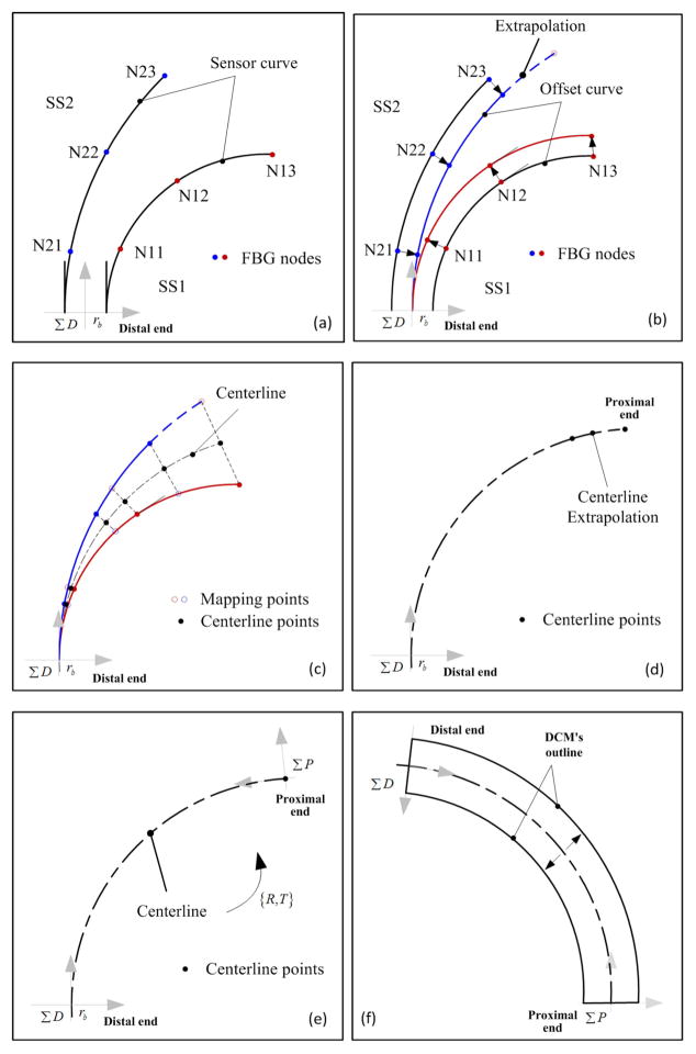
Fig. 4.
Schematic diagram for the shape reconstruction method. (a) SS1 -Shape sensor 1. (b) SS2 - Shape sensor 2. (c) N11, N12 and N13 - Three FBG sensing nodes along SS1. (d) N21, N22 and N23 - Three FBG sensing nodes along SS2. (e) ΣD - Distal coordinates system. (f) ΣP - Proximal coordinates system.

