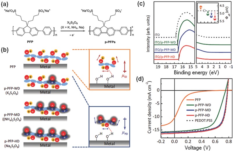
Figure 12.

a) Schematic synthesis of p‐PFPs by oxidative treatments of n‐type PFP with persulfate salts. b) Illustration of p‐PFP configurations with varying degree of doping concentration (left) on metal electrodes and their plausible dipole formation (right) at interfaces between the electrode and n‐type PFP (right upper image) or p‐PFP (right lower image); sky blue: π‐conjugated backbone, red (−): alkyl side chain bearing a sulfonate functional group, blue (+): oxidized π‐conjugated backbone, yellow (+): a sodium counter ion, red dashed line: electrostatic interaction between sulfonate ion and hydrogen. The red and blue arrows represent the dipole direction of the ion‐induced dipoles (μ ID) and polaron‐induced dipoles (μ PD), respectively. c) Ultraviolet photoelectron spectroscopy spectra of the ITO with and without p‐PFPs. The inset displays the effective WFs of the ITO (open circle) coated with thin AILs of PFP (orange), p‐PFP‐WD (olive), p‐PFP‐MD (blue), and p‐PFP‐HD (red). d) J–V characteristics of the OSCs using different AILs. Reproduced with permission.266
