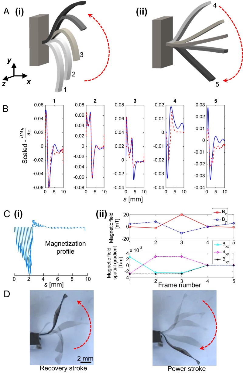
Fig. 4.
Programming an artificial cilium. (A) Extracted 2D natural cilia motion as expressed in Cartesian coordinates. The motion pattern includes two strokes: (i) the recovery stroke and (ii) the power stroke. The key time frames used by the artificial cilium are associated with a corresponding frame number. The time difference between each time frame is 0.2 s. (B) Optimization results for the desired first derivative of the bending moment to achieve the cilium motion. Each plot represents the desired first derivative of the bending moment of the beam for one time frame. The frame number is represented by the number at the top of it. The blue lines represent the desired first derivative of the bending moment, and the dotted red lines represent the obtained first derivative of the bending moment created by the magnetic actuation. The x axis for each frame corresponds to the length of the beam, ranging from 0 to 10 mm. The first three frames were given more weight during the optimization process because they were deemed to be more important. (C, i) The required magnetization profile and (ii) the magnetic field and its spatial gradients for the cilium (see Fig. S6 for a more quantitative representation for the magnetization profile). Using the coordinate system in A as a reference, the variables and in the magnetic field plot represent the x-axis and y-axis components of the magnetic field, respectively. The spatial gradients , , and represent , , and , respectively. (D) Snapshots extracted from the movie of the beating artificial cilium. Additional parameters for this device can be found in S9. Parameters for Each Case and Table S1.

