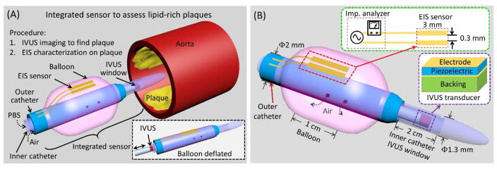
Figure 1.
(A) Conceptual scheme depicts the deployment of the integrated sensor consisting of an EIS sensor and an IVUS transducer to assess lipid-rich plaques. The IVUS sensor visualizes the aorta lumen, and the imaging information provides guidance for EIS characterization of the plaques by aligning the EIS sensor (2-point electrode) at the plaque. PBS: Phosphate-buffered saline solution. (B) The design of the integrated sensor highlights the mechanism for IVUS-guided EIS measurement. The IVUS transducer is positioned inside the inner catheter (ID: 1 mm, OD: 1.3 mm) with an imaging window of 2 cm to 10 cm. The EIS sensor is affixed to the balloon, which is anchored to the outer catheter (ID: 1.7 mm, OD: 2 mm). External pump generates air pressure to inflate or deflate the balloon, ranging from 2.3 mm to 6 mm in diameter.

