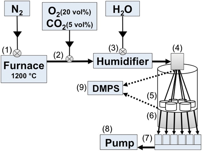
Figure 1.

Schematic illustration of the electrostatic air–liquid interface exposure system. (1) Silver nanoparticles are generated in a high temperature furnace (1200 °C). (2) Particles are transported further in N2, into which a mixture of O2 and CO2 is added. (3) Aerosol is humidified, and (4) particles are charged with a bipolar charger. (5) Aerosol is directed into six separate exposure chambers, two of which are equipped with filters. (6) Particle deposition is enhanced by applying an electrostatic force between the aerosol inlet and an electrode underneath the exposure chambers. (7) Critical orifices control the aerosol flow rate individually for each exposure chamber. (8) Aerosol is driven through the system by a pump. (9) Alternatively, the aerosol is directed to a DMPS for on‐line particle characterization either before or after the exposure chambers. DMPS, differential mobility particle sizer.
