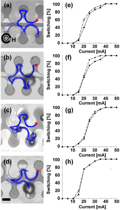
Figure 4. Repulsion transistors.
The horizontal and vertical magnetic field components are fixed at 50 Oe, while the in-plane field component rotates clockwise at a driving frequency of 0.1 Hz. The gate currents required for reliable switching in each of the transistor geometries are (a) 35 mA, (b) 30 mA, (c) 35 mA, and (d) 30 mA, respectively. The blue dotted lines depict the trajectories of magnetic particles, which are extracted from video data. The red circles depict the starting points of the overlaid trajectories, and the curved black arrow represents the rotation sense of the horizontal field component with the direction of the vertical field is depicted at the center of the curved arrow. Four example trajectories are also shown in Supplementary Movies S5-S8. The switching thresholds for 8.4 μm beads (solid lines) and 15.6 μm beads (dashed lines) for the transistors depicted in a-d are shown in e-h. Scale bar, 10 μm.

