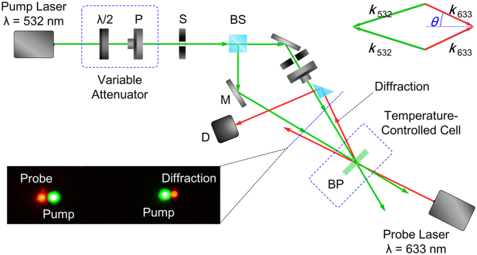
Figure 2. Experimental setup.
Schematic depiction of the experimental setup for volume hologram grating formation and the wave vector (phase) matching condition for the four wave mixing process (shown in upper right corner) involving the two writing beams [wavelength = 532 nm] and the probe and its diffraction [wavelength of 633 (632.8) nm]. Here P: polarizer; BP: a-BPLC sample; S: mechanical shutter; BS: beam splitter; λ/2: half-wave plate; D: photodetector; M: mirror]. The photo insert on lower left corner shows the writing beams, the probe beam and the diffracted beam on the screen.

